Hi
that mv reading on the solar setup is rounded
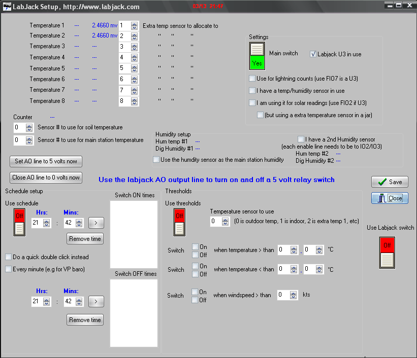
now, you need to set the labjack sensor to use to 2
Hi
that mv reading on the solar setup is rounded
now, you need to set the labjack sensor to use to 2
Sorry Brian… I’m a bit messed up.
Labjack sensor #2 is FIO3 input. My solar sensor is at FIO2 that seems to be Labjack sensor #1, as stated on Labjack setup.
Regarding rounded data at solar setup… could it be a units bug?:
1.- Labjack setup shows extra temp #1 as volts (0.1364 volts, or 136.4 millivolts)
2.- Solar sensor setup ask me for max millivolts. So 136.4 mv over a max 350.0 mv range should be about 39% solar.
3.- Current solar readings shows 0.1 millivolts (0.0001 volts) and 0% solar.
So the bug is in literals or in math?
for 1, i should have put there mv and v for the units
FIO2 is sensor 1 in the labjack setup and in the solar setup
FIO3 is sensor 2,etc
If using an LM335 or the EI-1022 from us, you need to use the “Special 0-3.6” range on the LabJack U3 analog inputs. That means make a differential analog input request and set the negative channel to 32.
With a raw SHT1X or SHT7X sensor, note that you at least need a pull-up resistor on the data line. See the Sensirion datasheets and app notes for recommended external components.
Hi
i looked at the U3 docs and figured that might be one way to get to be able to use over 2.4 volts
do you have any Delphi or c++ code samples for how to set the labjack into that mode?
(Maybe there is in the u3 docs (i think from memory i did see something there)
i tried setting the output voltage to drive the EI-1022 to only 2.5 instead of 5, but that meant the voltage coming back was not changing much with temperature changes
if the voltage coming back from the EI-1022 could be halved with a resistor, and then doubled again in the code, would that work?
Daytime now, and I made a quick test (more this afternoon). I have running both WD and DAQFactory, measuring FIO2 input (solar sensor). DAQFactory gives me now 0.299 volts (85% solar over a max 0.350 volts). WD reads 0.156 volts on Temp #1 at Labjack Setup, significantly below the DAQFactory reading.
I also noticed that Solar Setup…1 wire-Labjack setup must be wrong when asking for max mv for the solar sensor. I think it is really reading volts, not millivolts. Adjusting 1.0 mv (they are really 1.0 volts) gives a 18% solar with the actual 0.156 volts reading (0.156 / 1). Brian, can you double check that please?
try my test program again to see what it shows for the FIO2
I tried. WD, your test program and LJControlPanel give the same value read from FIO2. So the problem is running DAQFactory at the same time than WD.
But the millivolts issue remains. WD does not make the correct solar percentage. Even more, if I put any value from 0.0 to 0.9 in 1-wire/Labjack max mv setting, solar percentage drops to 0%. I put 1.0 and everything starts to work, giving lower than normal values but working. That’s why I think there’s some kind of bug there.
i looked at the U3 docs and figured that might be one way to get to be able to use over 2.4 volts do you have any Delphi or c++ code samples for how to set the labjack into that mode? (Maybe there is in the u3 docs (i think from memory i did see something there)
There is an example request in the pseudocode in Section 4.3.3 of the LabJack U3 User’s Guide. If using the Add/Go/Get method, you use the IOType “LJ_ioGET_AIN_DIFF” and set the negative channel to 32 (x1=32). If using eAIN(), you just set ChannelN=32.
So you don’t need to divide those temp sensor signals for the U3, but for general information about handling higher voltages see Section 2.6.3.6 of the LabJack U3 User’s Guide.
Here is how I have the LM335 connected up. The attached is just a redrawing I did of a design I found on the net years ago. The 10K resistor can be eliminated but I want to be able to set the sensor more closely.
The note above about setting the negative channel to 32 is important to set the range to 0-3.6vdc.
I also have a conversion to degrees f used:
(Value/.01-273.15)*9/5+32
Sensor Design.pdf (38.1 KB)
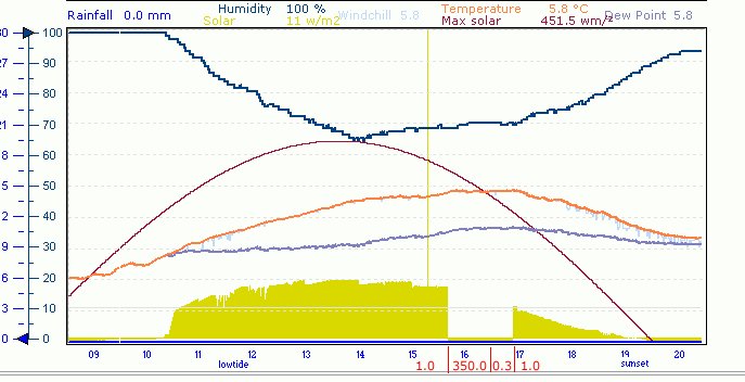
Below is a picture of the results of my U3 sensor readings using 10.37c-12.
Sensors:
FIO0 - open
FIO1 - LM335AZ
FIO2 - LM335AZ
FIO3 - LM335AZ
Sorry, thought I did.
“I know they say something is the first to go but I can’t remember what.”
seem to be missing the picture?
A whole testing day, and here are my conclusions:
I have conditioned the signal my solar sensor gives, connecting a resistor across the solar cell terminals to drop voltage to a max 0.350 volts (350 mv), working this way in the constant comsumption zone, and making the voltage as a linear function of the solar radiation received. So my 100% solar is a 350 mv readout on the Labjack FIO2 terminal.
On WD Labjack sensors setup I
just a recap
do you think one problem is that the U3 is reporting a mv reading when wd is expecting a v reading for the 1 solar
i.e if i *1000 the reading for the solar voltage from the U3 that would help
?
Maybe… We can test that way and see what happens.
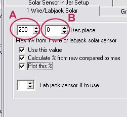
Any sensor you could use with a U3 should give a maximum 3 volts signal. That is 3000 mv. So you can set it on the “A” selector (see below pic). “B” selector would then be usefulness. This way you can easily do the math: (current reading / “A” selector) * 100 = % solar.
Or you can put entire volts on “A” selector, and millivolts on “B” selector up to 3 decimal places. 0 “A” and 350 “B” should read as 0.350 volts, or 350 millivolts. I think this is where the mess is done.
First option is simple, clean and easy for the user to understand.
what is the maximum voltage reading showing in the labjack setup in bright sunlight?
I can change it with an adjustable resistor, conditioning the signal in order to meet a linear proportional response. Right now it should be 0.350 v for my sensor.
ok, i think thats the problem
thats higher than what is expected (200mv)
i.e i need to change it so that you can set that 200 setting higher, i,e in your case, to 350
yes?
Yes, I think that should work.
But, why the 200 mv limit?