Hi all,
is there a way to set an offset for Davis VP solar sensor? After extending the cable length with original davis cable, the sensor show always a minimum of 5 wm/2.
Thank u for help
Hi all,
is there a way to set an offset for Davis VP solar sensor? After extending the cable length with original davis cable, the sensor show always a minimum of 5 wm/2.
Thank u for help
When mine started to show values above zero at night it was because it had started to fail and had to be replaced. Mine is extended as well as it is on the roof with the anemometer and the ISS is in the garden. No issues with a good sensor when extended, although I would suggest double checking the cable for any bad joints.
Stuart
How long is the extension? I agree with Stuart, extending the cable (which I have done for years) will not normally have that result.
Mine too is extended 10m and ok, it wasnt when i 1st connected it up, it was showing 1200+, one of the pins had crossed during
wiring, so i agree with Stuart too, check ya connections…
It depends how long the cable you need.
The sun sensor operates on the principle of photoresist.
That means when it comes sunshine from its resistance increases.
This applies the cable is longer the stronger must be its cross-section to prevent accretion resistivity.
I had the same problem when I stayed the night sown power to 5 watts.
I used copper cable with a diameter of 0.51 mm hard and now I have drawn on the roof of a house about 45 meters and has been operating for two years without a problem.
I’m sorry, but this post about the operating principle of the Davis sensor is incorrect. The Davis sensor does not operate on photoresistance. It uses a PIN photodiode to generate a photocurrent which is amplified and converted to a voltage by an operational amplifier (Op Amp). The output of the sensor is a voltage which varies linearly with solar radiation. It is correct that a large increase in the resistance of cable will affect the reading. The Davis specification does comment on the effect of a long cable, but the result is unlikely to be as described by the first poster unless there is a problem with the cable/connections.
So I see that you are obviously interested ![]()
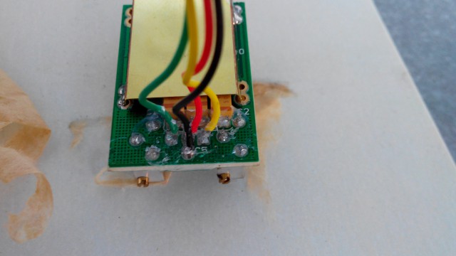
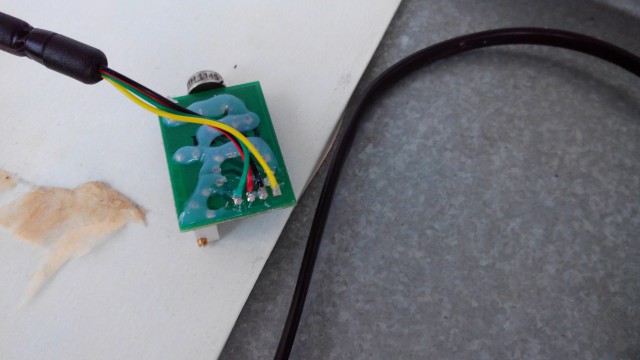
At first glance, the sensor can not detect principle but from what you see in the picture could it be.
If it’s a photodiode or phototransistor can not immediately recognize.
Only what is certain is that the red and black cable is connected to the PCB in one place in order to prevent an increase in resistance.
This applies to both solar and UV sensors.
Bottom line here is I believe providing the extension is no longer that the standard one allowed for the anemometer by Davis then it should work fine as I and others can attest from practical experience. The fact that it shows 5 W/m
I have repaired, and built (and helped others build) similar sensors a number of times. It’s a classic Op-Amp photodiode amplifier circuit you will find in almost any electronics textbook. The circuit as I describe is correct, but here’s the data sheet which you may find more credible ![]()
Only what is certain is that the red and black cable is connected to the PCB in one place in order to prevent an increase in resistance. This applies to both solar and UV sensors.
My understanding is that the ISS circuit detects that a UV or solar has been plugged in when it senses that those two are connected.
My UV\Solar are extended with about 33m of thermostat cable (18 awg) and they read fine. When I had readings at night I found that I had a wet connection from where I spliced the cables together. I cleaned that up and the sensor went back to reading 0 at night.
The extension is about 10m with original davis extension cable. I would check the connection. Thank you all for your hints and notes.
Greetings from germany
Am not sure if this is the right place to ask - I had my solar sensor extended by approximately 20 meters (65ft) and it worked OK. To catch as much sun as possible, I’ve displaced it to approximately 30 meters (100ft) in total. My cable is Cat5 with a 4-pin RJ connector. During night time the reading is 0 W/m2. But during the bright sunny day (as today), I see an offset to expected value. I didn’t have this offset with a previous setup (20m). I attached a photo that shows today’s reading.
Is it normal that long cable contributes to lower signal amplitude? Shall I put a correction factor (e.g. 1.15) to the reading?
Thanks.
See Stuart’s Solar Sensor FAQ for background on solar sensor measurements and predicted max solar values. In short it is unlikely that your actual solar readings will match exactly the WD estimated ones and you should not use that as a guide for calibration.
There will be a small reduction in the reading and accuracy due to extra cable length but normally a lot less than 15%.
Thanks, I’ll check that. I’m just curious since before the 20m->30m extension, read/expected values matched very well.
Unless you can do a direct comparison of measured values on a clear day it’s hard to be certain just what effect the extra cable is having. Cat 5 should be 24 AWG or better which is equivalent to the phone cable Davis uses. Since there are 8 cores and you only need 4 I would parallel them up to minimize the resistance.
If you really want to adjust something I would suggest adjusting the estimated solar max rather than Davis reading.
